Speedometer Material Rendering
Speedometer GUI element made entirely of Unreal shaders
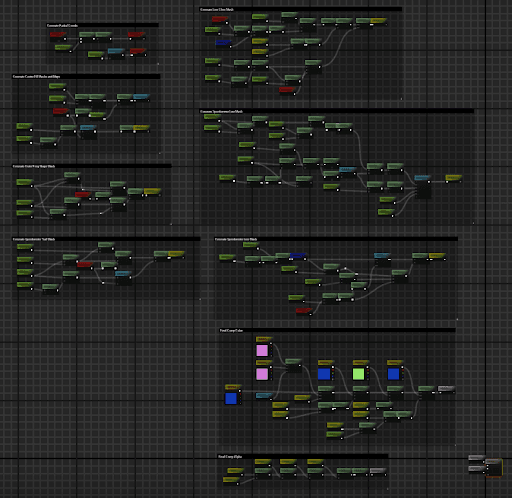
A lot of my experience working in the automotive sector involved creating procedural materials to save on texture memory overhead. When I was given this project to replicate as part of a skills test I noticed that the provided assets were very texture heavy. Texture memory tends to be very limited on cluster hardware, so I opted to recreate the assets with a procedural shader instead of binding textures.
Below is a step by step breakdown of how I did the speedometer in the center of the cluster.
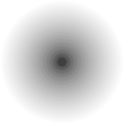
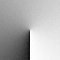
First, two grayscale coordinate maps are generated. The first is a simple distance map from the center of the shader area, and the second is a clockwise radial map for generating slices or radial gradients.

Other projects
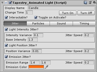
Tapestry - A Creation-Kit Inspired Unity Plugin
Using the backbone of design of Bethesda's Construction Kit applications for Morrowind and Oblivion, this plugin seeks to emulate the ease of use of creating levels

Magichem - A Minecraft Mod
Continuing the legacy of Thaumcraft with an addon for Mana and Artifice. Currently in active development.